Description
This article explains how to monitor the physical links of HP Virtual Connect with Hardware Sentry.
Procedure
To monitor the physical links of HP Virtual Connect, you will have to:
- Enable SNMP for VC-FC and VC-Enet modules from the Virtual Connect Management Console
- Add a remote monitoring of each switch using the following connector: MIB-2 Standard SNMP Agent - Network Interfaces.
The overall status of interconnect modules will be monitored separately by monitoring the chassis’ Onboard Administrator.
Step 1: Enabling SNMP for VC-FC and VC-Enet Modules
- Connect to the HP Virtual Connect Manager
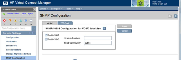
- In the left tree-view, select Domain Settings > SNMP Configuration
- Enable SNMP for both VC-FC and VC-Enet modules:
-
Select the VC-FC tab
-
Check the Enable SNMP and Enable SMI-S boxes
-
Specify a Read Community (e.g.: public)
-
Click Apply
-
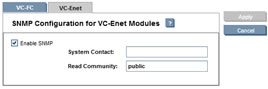
Select the VC-Enet tab
-
Check the Enable SNMP box
-
Specify a Read Community (e.g.: public)
-
Click Apply.
-
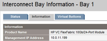
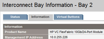
Step 2: Adding a Remote Monitoring
Each interconnect bay will have to be monitored individually. The IP of the interconnect bay can be found in the HP Onboard Administrator:
-
In TrueSight, configure the monitoring of the interconnect bay:
-
Create a new policy or edit an existing one
-
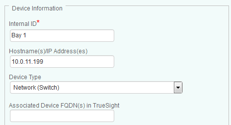
Under the Device Information section:
- Enter an Internal ID
- Enter the IP Address of the interconnect bay
- From the Device Type pull-down list, select Network (Switch).
-
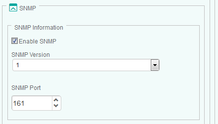
Scroll-down to the SNMP section, Enable SNMP and provide the SNMP Information.
-
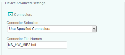
Under the Device Advanced Settings section:
- From the Connector Selection drop-down list, select Use Specified Connectors.
- In the Connector File Names field, enter MS_HW_MIB2.hdf
-
Click OK
-
Resume the procedure to configure the monitoring of each interconnect bay.
-
-
Click OK and Save.
Four different types of ports will be discovered:
- “d” Ports are the physical connections between the Virtual Connect Switch and individual Blades
- “eth” Ports are the management ports of the Virtual Connect Switch
- “tap” Ports are the ports that link the Virtual Connect Switches to each other for management purposes.
- “X” Ports are external ports or data links between Virtual Connect Switches.
All ports are reported as “Ethernet” by the Virtual Connect Switch regardless of their actual configuration.